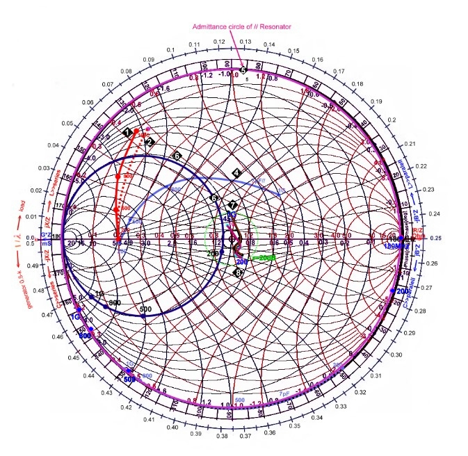
Finally, verify your design by calculating or measuring the S-parameters of your matching network and check if they meet your specifications. There are various methods like constant resistance circles, constant reactance circles, or constant VSWR circles that can help you find an optimal path and component values. This tool is javascript so it works on Windows, Mac, IOS, Android. After selecting a matching network topology, such as a series or parallel L-network, a pi-network, or a T-network - each with their own advantages and disadvantages - use the Smith chart to find the values of the components that will transform the load impedance to the source impedance along a path on the chart. This free online interactive Smith chart tool is a calculator which can help you design matching networks and obtain maximum power transfer between your source and load. Then plot the normalized load impedance on the Smith chart and locate the point that corresponds to the normalized source impedance - this is your target match. To use Smith charts for designing matching networks, you must first determine the impedance of your source and load at the operating frequency, and normalize them to the characteristic impedance of your transmission line.

Impedance Matching is the process of removing mismatch loss. The Smith Chart makes this easy to visualize.


Matching networks can be composed of passive components, such as resistors, capacitors, and inductors, or active components, such as transistors and amplifiers. On this page, we'll start the beginning of impedance matching, by illustrating the effect of a series inductor or a series capacitor on an impedance. One of the applications of Smith charts is to design matching networks, which are circuits that modify the impedance of a load to match the impedance of a source. We can use the Smith Chart to perform inpedance matching.


 0 kommentar(er)
